
Optimized Liquid Air Energy System (OLAES)
General Description
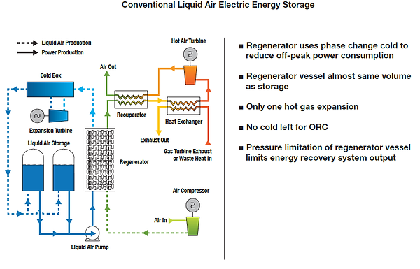
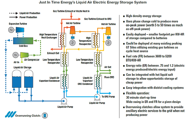
The Optimized Liquid Air Energy System (OLAES) is a vast improvement over conventional LAES technology which uses a high pressure regenerator to save the cold from vaporizing the liquid air in order to reduce the off-peak power consumption when making the next batch of liquid air. The OLAES system uses the vaporization cold to make more of the valuable on-peak power. The key to our new technology is the recondensing of the initially pumped stream of the stored liquid air (after vaporizing, heating, and expanding in a turbine to produce power) against the initially pumped stream to form liquid air at about 450 psia and -200°F. The initially pumped fluid provides the cold necessary for the recondensing, while the recondensing provides the heat required to vaporize the initially pumped steam. The recondensed stream is then repumped, vaporized, heated, and expanded down to atmospheric pressure to produce additional power. The cold available from the vaporizing of the -200°F, 450 psia liquid air can be used to condense the working fluid of an organic Rankine cycle (or absorb the heat rejection of a Brayton cycle) to produce additional power, or used for gas turbine inlet air cooling or provide chilled water to a district energy system, serve other refrigeration needs, or a combination of these uses.
The two generalized figures below compare the conventional LAES system to the OLAES system:
Removing the high pressure cryogenic material regenerator makes it practical to operate at pressures to 2000 psia or more, compared to a practical pressure limit of about 1000 psia for the single pumping and expansion in a system with a regenerator. The higher expansion ratio resulting from the higher operating pressure means more power extracted from the heated air flowing through the expander turbines. The high expansion ratio in the second expansion allows for a two-stage expansion with re-heating between stages, increasing the system power output and efficiency.
The primary heating source (and the source of about 20% to 30% of the total system power output) is typically a gas turbine, but for smaller systems a modern reciprocating natural gas engine is a good match for the OLAES system. The OLAES system can be configured in multiple ways depending on various parameters such as:
-
System size
-
Primary heat source
-
Cost of fuel
-
Value of produced power
-
Cost of input power
-
Cost of capital
-
R.O.I. target
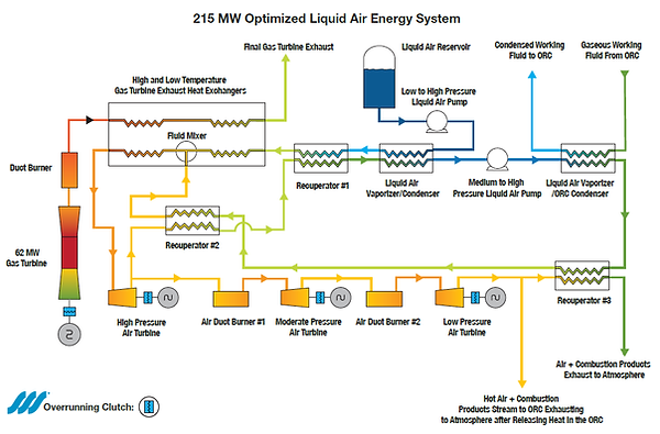
Following is a diagram and detailed description of a typical OLAES system:
(Referring to the above diagram) Liquid air, stored in a near atmospheric pressure reservoir at about -320°F, enters the OLAES system at the suction inlet to the Low to High Pressure Liquid Air Pump and pumped to about 1500 to 2000 1600 psia, then vaporized in the vaporizing side of the Liquid Air Vaporizer/Condenser, the gaseous air is then heated in the Recuperator #1, additionally heated in the Low Temp. GT Exhaust Heat Exchanger, mixed with the second pumped gaseous air stream at the Fluid Mixer, next the combined stream is further heated in the High-Temperature GT Exhaust Heat Exchanger. The heated combined air stream is directed to the High Pressure Air Turbine where the air is expanded to about 450-500 psia and producing power to drive a generator, the hot exhaust air stream from this turbine splits, with a portion directed to Air Duct Burner #1, with the remaining flow entering Recuperator #2 where heat is extracted and returned to the cycle, the reduced temperature air stream then flows to the above mentioned Recuperator #1, returning more heat to the cycle. The cooled air stream at about 100°F and 450-500 psia then flows to the condensing side of the Vaporizer/Condenser, where the air is re-condensed to the liquid phase at 450-500 psia and about -220°F. The cold re-condensed liquid air stream is directed to the Moderate to High Pressure Liquid Air Pump where it is re-pumped to about 1500 to 2000 psia. The re-pumped liquid air stream is vaporized in the Liquid Air Vaporizer/ORC Condenser leaving at 1500 to 2000 psia and a temperature of from -70F to +40F depending on the configuration of the ORC and whether some of the cold is used for gas turbine inlet air cooling. The cool high pressure vaporized re-pumped stream of air is then heated in Recuperator #3, then heated further in Recuperator #2 and directed to the Fluid Mixer where it joins to make the above mentioned combined stream, the re-pumped portion of the combined stream after heating in the High-Temperature GT Exhaust Heat Exchanger, and expanded in the High-Pressure Air Turbine (less any recycling) is split off from the combined stream and enters the above mentioned Air Duct Burner #1 at about 450-500 psia and heated by the combustion of fuel in the duct burner to about 900°F to 1000°F, the hot pressurized air is expanded in the Moderate-Pressure Air Turbine down to about 75-150 psia producing additional power. The expanded air from turbine is directed to Air Duct Burner #2, heated by combustion of fuel in the duct burner to 900°F to 1200°F and then expanded down to near atmospheric pressure in the Low Pressure Air Turbine producing additional power. The moderately hot air stream (with combustion products) exiting the Low Pressure Turbine is split with a portion transiting Recuperator #3, returning heat to the cycle, and then exhausting to atmosphere, with the other portion of the moderately hot air stream directed to the organic Rankine Cycle (ORC) (not pictured), providing heat to the ORC (which provides about 10-15% of the total system power) and exiting the ORC at atmospheric pressure. The flow of the re-pumped stream can be as much as 25% greater than the inlet mass flow to the system, with this extra recycled mass producing additional power, and then being recondensed in the condensing side of the Liquid Air Vaporizer/Condenser. An additional heat exchanger using molten salt heated with renewable electric energy can be installed between Recuperator #2 and Mix #1, decreasing the fuel rate and increasing the power output and overall system economics at the expanse of a slightly decreased energy ratio.
The system has considerable operational flexibility by adjusting various parameters such as the temperature out of the two duct burners, the amount of liquid salt heating, the inlet
temperature to the air turbines, and the amount of recycling. Using a Siemens SGT-800 gas turbine, the power output of the above system can be adjusted between about 200 MW to over 235 MW with the heat rate varying from approximately 3900 BTU/KW-HR to 4700 BTU/KW-HR and the energy ratio between .90 and 1.25. By replacing the low-pressure air turbine and combustor with the combustion end of a gas turbine the fuel rate can be as low as 3400 BTU/KW-HR.
The liquid salt to air heat exchanger uses hot liquid salt heated with excess renewable power using electrical resistance heaters and stored in hot and cold insulated tanks. The air liquefaction system is designed to operate for multiple hours (usually 6 to 10 hours each night and longer on the weekends). Due to the startup time of the air liquefaction system, it is impractical to store short bursts of excess renewable power as liquid air. Instead, the liquid salt system is used to store the excess renewable energy that is often available for 30 minutes to up to 3 or more hours on many sunny windy afternoons. The liquid salt storage
system can be turned on and off almost instantly. This excess power if not stored would be curtailed, and therefore is usually available at low cost.
There are multiple of ways to configure the cycle to match various prime movers and specific site requirements. When matched with an intercooled gas turbine, the cycle is configured to utilize both the high temperature exhaust heat and the moderate temperature air from the first stage air compressor, returning cooled air to the second stage compressor, bypassing the intercooler. This same concept is used when the cycle is matched with a turbocharged natural gas engine, using the heat both from the engine exhaust and the hot air from the turbocharger, bypassing the aftercooler, and returning cooled air to the engine intake manifold. See the patent section of the website where there is a link to Just In Time Energy’s patent which includes 5 other system diagram arrangements.
The SSS Overrunning Clutches shown between the generators and the gas turbine and the high-powered hot air turbines in the above system allows the generators to be used to provide ancillary services to the grid when the OLAES system is not being used to return stored energy to the grid. These services include spinning reserve and reliability credits, black start capability, and grid voltage and frequency support from the generators provided with the overrunning clutches. These services become more necessary as the penetration of intermittent renewable power on the grid increases.
These links provide general information about ancillary services.
https://en.wikipedia.org/wiki/Ancillary_services_(electric_power)
https://www.ieso.ca/ancillary-services
General – wherever there is a substantial amount of excess renewable energy available at certain times and a need for moving it to times where the renewable sources can’t meet grid demand.
Main Transmission Connected Storage – 50 to over 700 MW
Microgrids - University and Commercial Campuses 30MW to 150 MW
The OLAES system is scalable from about 30 MW to over 700 MW. Electric energy storage in MW-HR is up to at least 200 times the MW rating (i.e., at least 200 hours of non-stop power generation), set by the size of the liquid air plant and the liquid air storage tank(s) and system operating profile. The system can be matched with 10 to 20 MW turbocharged gas engines or gas turbines from 5 MW to well over 100 MW. The fuel rate can range from 3200 BTU/KW-HR to 4500 BT/KW-HR and the energy ratio, ER (electric energy produced divided by the electric energy used to produce the LNG and any stored heat) between 0.8 and 1.2. In general, the fuel rate improves with decreasing ER.
d
d
Detailed Description
Applications
Scalability
Combined Electric and Gas Storage System (CEGS)
The Combined Electric and Gas Storage System (CEGS) stores both electric energy and natural gas as LNG at off peak times. At peak times the LNG is returned in gaseous form to the pipeline system at the required pressure, while concurrently returning to the grid 85% to over 170% of the electric energy used to make the LNG at a fuel rate between 3900 and 5400 BTU/KW-HR. The key to this new technology is the recondensing of the initially pumped stream of the stored LNG (after vaporizing, heating, and expanding in a turbine to produce power) against the initially pumped stream to form a second stream of LNG at about 575 psia and -125°F. The initially pumped fluid provides the cold necessary for the recondensing, while the recondensing provides the heat required to vaporize the initially pumped steam. The recondensed stream is then repumped, vaporized, heated, and expanded a second time down to the receiving pipeline pressure to produce additional power. The cold available from the vaporizing of the -125°F, 575 psia LNG can be used to condense the working fluid of an organic Rankine cycle (or absorb the heat rejection of a Brayton cycle) to produce additional power. Or this cold can be used for gas turbine inlet air cooling or to provide chilled water to a district energy system or serve other refrigeration needs. It is the recondensing of the LNG against itself and the two power expansions that make the cycle unique.
The CEGS system has two primary revenue streams – the value of the electric energy returned to the grid and the value of moving the natural gas from off peak to peak times. In addition, the overrunning clutches included in the system provide the potential for grid ancillary services payments.
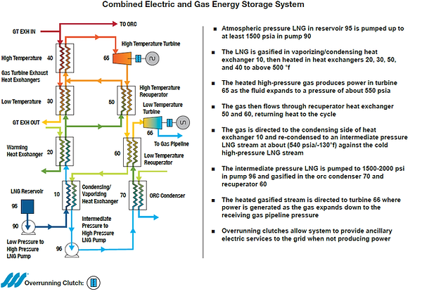
The figure below explains how the CEGS system works.
(Referring to the above diagram) LNG, stored in a near atmospheric pressure reservoir at about -258°F, enters the CEGS system at the suction inlet to the Low to High Pressure LNG Pump and pumped to about 1500 to 2500 psia, then vaporized in the vaporizing side of the LNG Vaporizer/Condenser, the gaseous LNG (mostly methane and referred to as methane in the remaining description), is heated in the Recuperator #1, additionally heated in the Low Temp. Gas Turbine Exhaust Heat Exchanger, mixed with the second pumped gaseous methane stream at the Fluid Mixer forming a combined methane stream. The combined methane stream is further heated in the High-Temperature GT Exhaust Heat Exchanger (note that a duct burner is located between the gas turbine exhaust and the High Temperature GT Exhaust Heat Exchanger). The heated combined methane stream is then directed to the High-Pressure Methane Turbine where the methane is expanded to near pipeline pressure producing power to drive a generator, the hot exhaust methane stream from the turbine is split, with a portion directed to the Moderate Pressure Methane Turbine and the remaining flow enters recuperator #2 where heat is extracted and returned to the cycle, this reduced temperature methane stream then flows to the above mentioned Recuperator #1, returning additional heat to the cycle, cooling the methane stream. The cooled methane stream, at about 100°F, exits Recuperator #1 and is directed to the natural gas pipeline. The portion of the flow exiting the High-Pressure Methane Turbine that is directed to the Moderate Pressure Methane Turbine is expanded to about 575 psia producing power, and then directed to the above-mentioned Recuperator #3, returning heat to the cycle, then flowing to the condensing side of the LNG Vaporizer/Condenser, where the methane is re-condensed to the liquid phase at about 575 psia and about -125°F. The cold re-condensed liquid methane is directed to the Medium to High Pressure Liquid Methane Pump where it is re-pumped to about 1500 to 2500 psia. The re-pumped liquid methane stream is vaporized in the Liquid Methane Vaporizer/ORC Condenser leaving at 1500 to 2500 psia and a temperature of about 40°F to 50F. The approximately 40-50°F high pressure vaporized re-pumped methane stream is then heated in Recuperator #3, then heated further in Recuperator #2 and directed to the Fluid Mixer where it joins to make the above-mentioned combined stream.
The flow of the re-pumped stream can be as much as 25% greater than the inlet mass flow to the system, with this extra recycled mass producing additional power, and then being recondensed in the condensing side of the LNG Vaporizer/Condenser. An additional heat exchanger using molten salt heated with renewable electric energy can be installed between Recuperator #2 and the Fluid Mixer, decreasing the fuel rate and increasing the power output and overall system economics at the expense of a slightly decreased energy ratio.
The ORC cycle is provided heat from the final gas turbine exhaust stream exiting the Low Temperature Gas Turbine Exhaust Heat Exchanger after heat is added to this exhaust stream in either an additional molten salt heat exchanger or in the Duct Burner shown in the diagram. The ORC provides about 15% of the total output power.
The system has considerable operational flexibility by adjusting various parameters such as the temperature out of the duct burner, the amount of liquid salt heating, the amount of recycling and system operating pressure. Using a Siemens SGT-800 gas turbine operating at full power, the power output of the above system can be adjusted between about 95 MW to over 110 MW with the heat rate varying from approximately 4800 BTU/KW-HR to 5100 BTU/KW-HR and the energy ratio between 1.0 and 1.7. The system can also operate at reduced load and LNG flow to meet required off design operating conditions.
The liquid salt to methane and liquid salt to the gas turbine exhaust stream heat exchangers use hot liquid salt heated with excess renewable power using electrical resistance heaters and stored in hot and cold insulated tanks. The LNG system is designed to operate for multiple hours (usually 6 to 10 hours each night and longer on the weekends). Due to the startup time of the LNG plant, it is impractical to store short bursts of excess renewable power as liquid air. Instead, the liquid salt system is used to store the excess renewable energy that is often available for 30 minutes to up to 3 or more hours on many sunny windy afternoons, in addition to storing excess nighttime renewable energy. The liquid salt storage system can be turned on and off almost instantly.
There are multiple of ways to configure the cycle to match various prime movers and specific site requirements. When matched with an intercooled gas turbine, the cycle is configured to utilize both the high temperature exhaust heat and the moderate temperature air from the first stage air compressor, returning cooled air to the second stage compressor, bypassing the intercooler. This same concept is used when the cycle is matched with a turbocharged natural gas engine, using the heat both from the engine exhaust and the hot air from the turbocharger, bypassing the aftercooler, and returning cooled air to the engine intake manifold. The turbines shown in the above diagram represent expansion steps, these expansion steps may occur in multiple turbines connected in series or parallel. If the turbines are the radial inflow type, multiple turbines may be installed on a common gearbox. In the diagram above the split between the flow directed towards the gas pipeline and the flow going to the condensing side of the LNG Vaporizer/Condenser could take place before the inlet to the High-Pressure Methane Turbine, with the Moderate Pressure Methane Turbine located in parallel with the High Pressure turbine, this would always be the case if the pipeline pressure is lower than the recondensing pressure.
See the patent section of the website where there is a link to Just In Time Energy’s patent which includes 5 other system diagram arrangements and descriptions.
The SSS Overrunning Clutches shown between the generators and the gas turbine and the high-powered methane turbines and generators in the above system allows the generators to be used to provide ancillary services to the grid when the CEGS system is not being used to return stored energy to the grid and stored gas to the pipeline system. These services include spinning reserve and reliability credits, black start capability, and grid voltage and frequency support from the generators provided with the overrunning clutches. These services will become more necessary as the penetration of intermittent renewable power on the grid increases.
These links provide general information about ancillary services.
https://en.wikipedia.org/wiki/Ancillary_services_(electric_power)
https://www.ieso.ca/ancillary-services
• At new or existing peak-shaving LNG the CEGS system will add a second revenue stream from the sale of on-peak power. Most peak shaving LNG plants only operate for a few hundred hours per year, adding the CEGS system could increase revenue hours to thousands of hours per year and make marginal projects an economic success.
• At LNG import terminals this new technology provides efficient power generation when re-gasifying the LNG. The system produces about 2500 KW per Kg/s of vaporized LNG, at a fuel rate considerably better than that of a modern combined cycle power plant. Nearly all the sea water pumping for regasification would be eliminated. The vaporized gas would leave the system at pipeline pressure.
• At LNG export terminals, this technology could facilitate arbitrage between spot market LNG sales and spot market power sales and provide ancillary electric grid services revenues.
• In parts of the country such as NY state and New England where there is both a need for on-peak power and natural gas, the CEGS system would store pipeline gas as LNG at off peak times, returning the gas to the pipeline system at peak times while concurrently returning more than 170% of the off-peak power used to make the LNG to the grid at a fuel rate significantly better than that of a modern combined cycle power plant. The system will increase the flow of natural gas to the pipeline system at peak times without the need for new pipelines or compressor stations.
• Natural gas storage sites that use depleted oil or gas production fields (about 80% of the gas storage sites in the U.S.) are a key opportunity for the CEGS system. At most of these storage fields, the discharge pressure decreases sharply as discharge flow increases at peak times. This limits the flow from the field and requires compression power to put the gas back into the pipeline system. By converting pipeline gas to LNG at off peak time using excess renewable energy and returning it to the pipeline system at the required pressure at peak times at a flow rate 3 to 4 times greater than the off peak flow rate into the LNG plant, the CEGS system provides high deliverability gas along with the normal free flow from the storage field while concurrently returning to the grid up to 170% of the off-peak power used to make the LNG at a fuel rate less than that of a modern combined cycle power plant. The CEGS system adds flexibility to gas storage while providing environmentally friendly power to support the grid when renewable electric energy is not available.
• At city gate connections between the mainline gas pipeline and the local gas distribution system, the CEGS system would produce LNG at night using mostly excess renewable electric energy returning the gas at peak times to both the mainline pipeline and a smaller amount to the lower pressure gas distribution system. Depending on the flow split between the high and low pressure systems, the fuel rate of the peak time power delivered to the grid could be as low as 4000 BTU/KW-HR.
• Electric Utilities – Using the CEGS system electric utilities can store gas in the form of LNG at off-peak times at a location relatively near their gas fueled power plants (compared to paying for storage at a site owned by someone else a thousand miles away) returning the gas to the pipeline at peak times while concurrently generating 90% to 170% of the electric energy used at off peak time to produce the LNG at a fuel rate better than a modern combined cycle power plant, and decreasing the need for operating inefficient peaking gas turbine generators.
The CEGS system is scalable from about 20 MW to over 500 MW with returning gas flows to the pipeline between 22 and 250 kg/s (equal to a gas flow rate of 100 to 1,000 MMSCFD). Electric energy storage in MW-HR is up to at least 200 times the MW rating (i.e., at least 200 hours of non-stop power generation), set by the size of the LNG plant and the LNG storage tank(s) and operating profile. A practical system could easily have a return gas flow rate of 3 to 4 times the flow rate into the LNG plant. The system can be matched with 5 to 20 MW turbocharged gas engines or gas turbines from 10 MW to well over 100 MW. The fuel rate can range from 4000 BTU/KW-HR to 5300 BT/KW-HR and the energy ratio, ER (electric energy produced divided by the electric energy used to produce the LNG and any stored heat) between 0.8 and 1.8. In general, the fuel rate improves with decreasing ER and the returned pipeline pressure.

General Description
Detailed Description
Applications
Scalability